Overview
A thorough assessment of the switchboard must be carried out prior to the alteration and addition of any supplementary supply to an existing switchboard.
It is important that every Licensed Electrical Worker understands the impact of these alterations and how these changes may affect many aspects of what the switchboard was originally designed and installed to handle. Even if there is physical space in the switchboard, the crucial conductive elements within the system (the busbars and interconnecting cables) have a finite capacity to handle current.
When additional loads are added without considering their impact on the existing setup, the system can become prone to overcurrent and overheating, which compromises the safety of the installation.
You should no longer assume that power is flowing in only in one direction from the grid. With the increase in the use of distributed energy resources like solar power and batteries, two-way energy flows such as supplementary supplies are becoming increasingly common. This creates additional heating, as the inverter and grid may now both contribute to current flow and temperature rise within the switchboard and components. The switchboard has been designed with careful considerations of current and heat. Where excessive current is being conducted, the switchboard may not be able to dissipate the heat as it was designed to do.
The switchboard assessment must ensure the summation of the grid supply circuit breaker (CB) plus the inverter supplementary supply CB will not exceed the current carrying capacity of any portion of the switchboard that will carry the total current.
Example 1 (Domestic installation with solar)
A domestic property has a common 18 Module switchboard enclosure. This switchboard uses the manufacturers fork type busbar rated to a maximum of 80 A (refer to figure 1).
The Main Switch (GRID) CB is 63 A.
The Main Switch (INVERTER) CB is 32 A (added for the solar/supplementary supply).
We now have a potential to generate 63 A + 32 A = 95 A from the two connected generation sources, exceeding the current carrying capacity of the 80 A busbar.
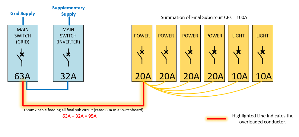
It is also common to find 10 – 16 mm2 jumper cables installed between CBs and busbars, the new generated total current greatly increases risk of an overload resulting in a fire (refer to figure 2).
Figure 1
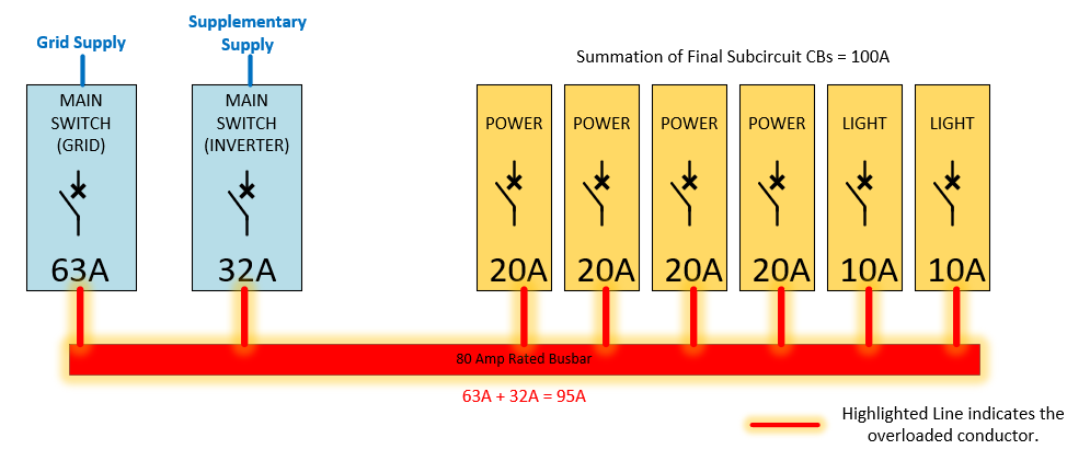
Figure 2
Example 2 (Domestic installation with solar and a separate a.c. battery)
A domestic property has a common 18 Module switchboard enclosure. This switchboard uses the manufacturers fork type busbar rated to a maximum of 80 A.
The Main Switch (GRID) CB is 63 A.
The Main Switch (INVERTER) CB is 25 A (added for the solar/supplementary supply).
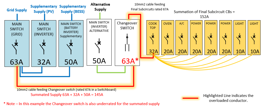
The Main Switch (BATTERY INVERTER) CB is 50 A (added for the battery/supplementary supply).
The Main Switch (ALTERNATIVE) CB is 50 A (added for the battery/alternative supply).
When the battery energy storage system (BESS) operates in the Alternative Supply mode, with a potential of 50 A, the conductors would not be overloaded.
However, if the BESS was able to function as a Supplementary Supply, we may potentially have 63 A + 32 A + 50 A = 145 A of potential supply generation. This may create severe overloading of the switchboard conductors.
The common 10 – 16 mm2 jumper cables installed between CB’s and busbars, are now severely overloaded. The risk of an overload resulting in a fire is now probable (refer to figure 3).
Figure 3
Example 3 (Industrial installation with solar)
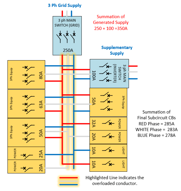
A factory has a standard 250 A 3-phase industrial switchboard enclosure with 3-phase busbars to feed the circuit protection equipment. The 3-phase busbars are rated to a maximum of 250 A.
The Main Switch (GRID) CB is 250 A.
The Main Switch (INVERTER) CB is 100 A (added for the solar/supplementary supply).
We now have a potential to generate 250 A + 100 A = 350 A from the connected generation sources, exceeding the current carrying capacity of the 250 A busbar.
This also creates a large risk of exceeding the temperature rise limitations of the designed switchboard and components. The components are not only at risk of fire from overcurrent, but also unable to dissipate the increased temperature for which the switchboard was designed and approved to safely function (refer to figure 4).
Figure 4
Australian Standards
AS/NZS 4777.1:2021 Clause 3.4.2 Overcurrent Protection
Any conductor within the electrical installation shall not be overloaded due to summation of current from grid supply and supplementary supply(s).
AS/NZS 3000:2018 Section 8.1.2 Verification – General Requirements
Where the electrical installation is an alteration or repair to an existing electrical installation, it shall be verified that the alteration or repair complies with this Standard and does not impair the safety of the existing electrical installation.
The full text of the Australian Standards can be purchased from the Standards Australia store.
NECA, NESMA and IEI have published a document regarding Supplementary Supplies consideration and compliance
Further information
Disclaimer
The above guidance provides practical and technical guidance. It does not constitute legal advice. Licensed Electrical Workers, Registered Electrical Contractors and Licensed Electrical Inspectors should seek independent advice about their obligations under the Electricity Safety Act 1998 and the Electricity Safety (General) Regulations 2019.
References to the Standards have been reproduced without modifications by Victorian Energy Safety Commission (ABN 27 462 247 657) with the permission of Standards Australia Limited.
Users must not copy or reuse this work without the permission of Standards Australia or the copyright owner.
Date: 29/06/2026 10:37
The currency and accuracy of this information cannot be guaranteed once printed or saved to a storage device. If in doubt, please check the Energy Safe Victoria website for the current version.